

Compiling a Logical Program
In this tutorial, we walk through how a logical program gets compiled for execution on Gemini Logical. In particular, we discuss compilation down to native gates, atom moves, and back up to a noisy SQUIN kernel (or onto the hardware).
First, you can define your logical program. Similar to the “Using the Gemini Logical Simulator” tutorial, we define a kernel that prepares a two-qubit GHZ state and annotates the physical measurements with detectors and observables.
from bloqade.gemini import logical, GeminiLogicalSimulatorfrom bloqade import squin@logical.kernel(aggressive_unroll=True)def logical_bell_state(): reg = squin.qalloc(3) squin.h(reg[0]) squin.cx(reg[0], reg[1]) return logical.default_post_processing(reg)For the rest of the tutorial, we will reference visual tools from Gemini Studio to see the various steps in the compilation pipeline. We recommend that you open https://bloqade.quera.com/studio/gemini/#circuit={version:13,qubits:3,gates:[{gate:h,column:0,targets:[0]},{gate:cx,column:3,targets:[0,1]}]} to follow along to visualize the various steps in the compiler pipeline.
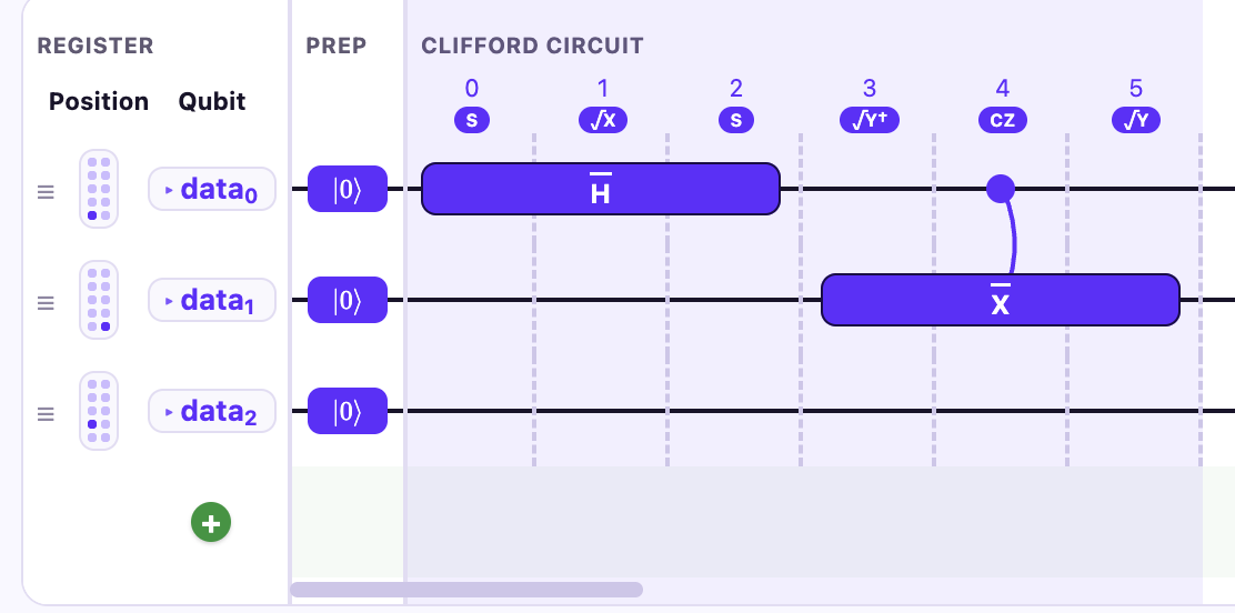
Our logical kernel can be visualized like above.
Conversion to Native Gates
Section titled “Conversion to Native Gates”The first step in the compilation pipeline is the conversion from SQUIN to Native gates. The native gates are the following:
| Gate | Description |
|---|---|
R(phi, theta, qubits) | Rotation about an axis in the X-Y plane given by phi, with magnitude theta, on qubits. |
Rz(theta, qubits) | Rotation about the Z axis by theta on qubits. Note that these are virtual gates and will be eliminated when rewriting to R. |
CZ(controls, targets) | Controlled-Z gate from controls to targets. |
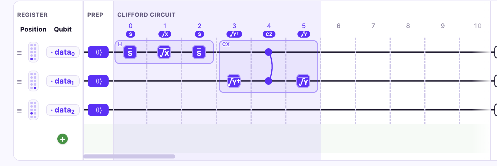
As we can see from Gemini Studio, we expand the Hadamard and CX gates into rotation and CZ gates that are native to the hardware.
Initial Layout
Section titled “Initial Layout”To find the initial layout for the atoms, the move compiler runs a layout heuristic based on the CZ interactions between atoms. As we can see in the Studio image below, the heuristic layout recommends placing qubit 1 in the same column as qubit 0 to minimize the number of moves needed, as depicted in the below image where we swap data qubits 1 and 2.
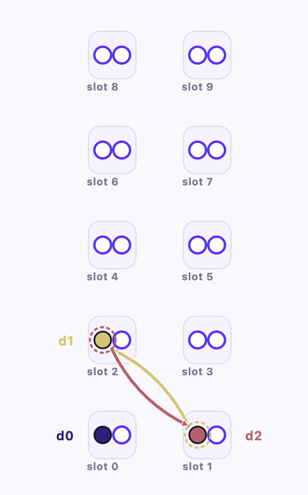
But why does placing qubit 1 in the same column as qubit 0 minimize the number of moves needed? At first glance, it might seem that putting qubit 1 in slot 1 makes it closer to qubit 0. The answer lies in the connectivity of the architecture, which we can explore using the ArchVisualizer tool.
from bloqade.lanes.arch.gemini.logical import get_arch_specfrom bloqade.lanes.visualize.arch import ArchVisualizerArchVisualizer(get_arch_spec()).plot_interactive()If you click “Show all buses”, then you will see that we have full bipartite connectivity between the left and right paired SLM sites within a column pair, and one connection between columns. This explains why, for this particular architecture, it is advantageous to put qubit 1 in the same column pair as qubit 0: it takes only one move to put qubit 1 next to qubit 0, whereas it would take two moves to put qubit 1 next to qubit 0 if they were in different column pairs.
If you wanted to try out other layouts yourself, you can do so using the
qalloc_atfunction, which takes in a list of integers representing slot indices on the processor. There are 10 possible “slots” where you can allocate your logical qubit on Gemini-QEC, which are depicted in Gemini studio above.
Move Scheduling
Section titled “Move Scheduling”Given the initial placement of the atoms, we can subsequently run our move synthesis compiler to schedule atom moves. Our move synthesis compiler employs a novel graph-based search algorithm (which we term “Entropy-guided search”) to find the sequence of atom moves for each CZ layer.
Atoms have to move back to their initial layout after each CZ layer for dynamical decoupling reasons.
logical_bell_task = GeminiLogicalSimulator().task(logical_bell_state)# We can see the result of the move synthesis compiler by visualizing the atom moves below.logical_bell_task.visualize(arch_vis=True)From the compiled atom move program, we can make the following observations:
- The Hadamard gate is converted into a native
Rgate. As was mentioned above, the localRzgates were eliminated and absorbed by theRgate. - Similarly, the CX gate is converted into native
RandCZgates. - For the CZ gate, we have to move qubits 7 through 13 next to qubits 0-6, respectively. The move synthesis compiler does so, and subsequently moves the atoms back to their initial layout for dynamical decoupling purposes.
Note that all qubits in a logical block have the same moves applied. This is intentional because
CZis transversal for the Steane code, and this significantly simplifies the move synthesis problem.
Further Lowering to Hardware, or Simulation
Section titled “Further Lowering to Hardware, or Simulation”From here, we can either further lower our kernel to hardware, or convert our move kernel to a noisy SQUIN kernel, which can subsequently be simulated. Below, we show how you can get the noisy physical SQUIN kernel for your compiled task.
physical_bell_squin_kernel = logical_bell_task.physical_squin_kernellogical_bell_task.tsim_circuit.diagram(height=500)
We can see that our physical SQUIN kernel is annotated with noise channels, based on the physical atom move program that we visualized. We can subsequently simulate our noisy SQUIN kernel.